Problem Statement of Transporter:
Build an autonomous robot which can traverse a grid and place blocks in voids on the grid such that it optimises its path while completing this task. For more details about the event, refer to our website.
As per the Problem Statement, the robot has to guide its locomotion and perform the tasks of
Grid following
Obstacle detection
Void detection
Moving block to void
Materials Required:
- Chassis
- 2 DC motors
- 2 Wheels
- 1 Castor Wheel
- 1 Development Board
- 1 Microcontroller (Atmega16)
- 1 Programmer
- 1 Motor Driver (L293D)
- Relimate Connectors
- 9 LEDs, 9 LDRs
- 1 IR Led, IR photodiode
In this Do It Yourself tutorial, the tasks of the robot have been divided into the following parts
- Locomotion of the Robot
- Chassis
- Sensors
- Processing
- Algorithm
Locomotion:
For locomotion, a simple differential drive is being used. In a differential drive, two basic motors can be used to run the robot in all the required manners. Given below, is a simple demonstration of a differential drive.
This is a basic H-Bridge differential drive. Given below is a table in which running motor in different directions results in different directions of motion.
| Right motor | Left motor | |
| 1 | 1 | Forward |
| 0 | 1 | Right |
| 1 | 0 | Left |
| 0 | 0 | Free run |
| 1 | 1 | Braking |
** 1 ->Motor movement in front direction 0 ->Motor movement in backward direction
You can also check our detailed tutorial on Differential drives.
Chassis:
Our transporter robot needs to move the block from one node to a void. Hence, the body of robot can’t be simple as a line follower. We need a mechanical provision to move the robot.
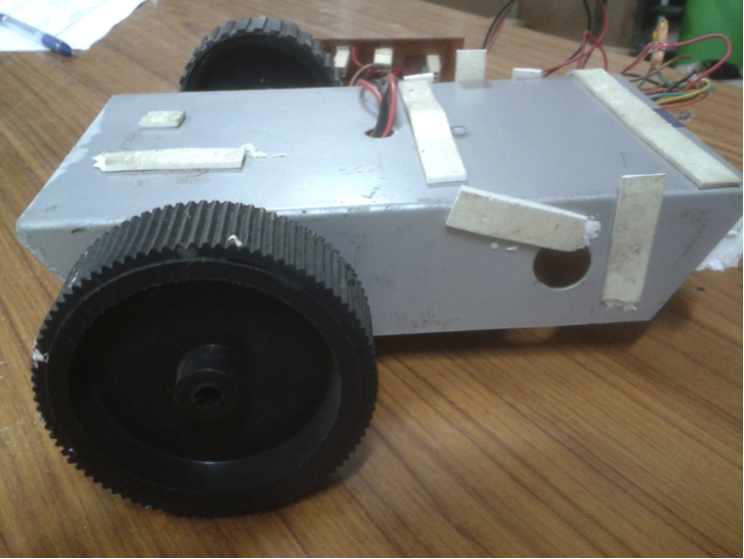
For the grid follower part, a simple differential drive will suffice. For moving the block, we can have special grippers attached to the robot as shown in figure.

The above picture is a top view of the chassis that needs to be made. 2 gripper arms are attached to the front of robot. These hands will help the robot to get hold of the block. The motor on the right hand (indicated by blue) can be used to lock the block and drag it to its destination. The motor rotates on a plane parallel to the grid surface.
Sensors:
In this event, we need to sense – line/grid, block and void.
Grid following
For grid following, we are using simple LED LDR sensor circuit. 5 LED-LDR pairs placed collinearly can be used for line following.
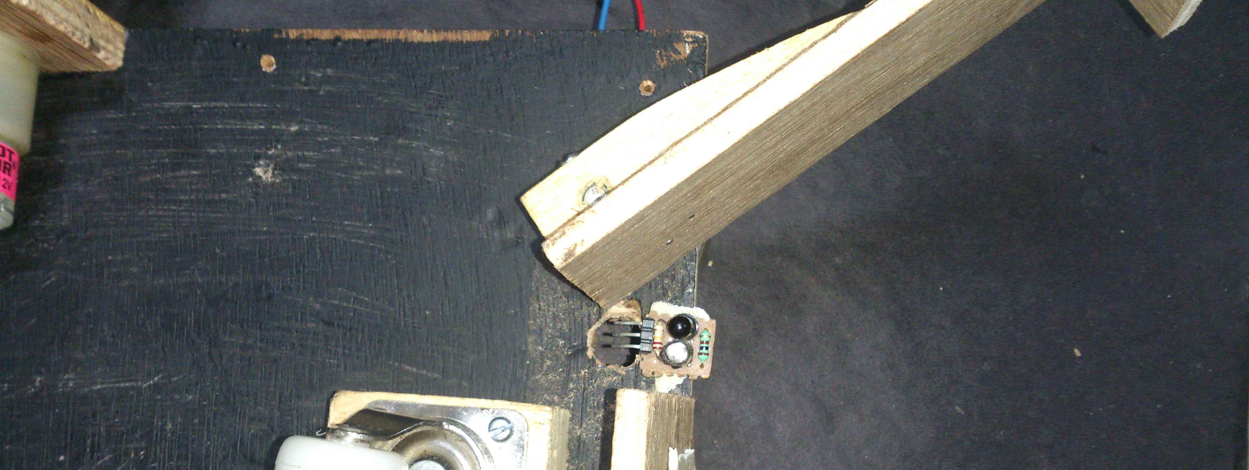
Apart from these, we will need 1 sensor for node detection. This node detecting sensor will be placed near the motors as shown in figure. Placing this node detecting sensor near the motors facilitates zero radius turn on the node.

The figure below shows soldered circuit of line following sensor circuit.
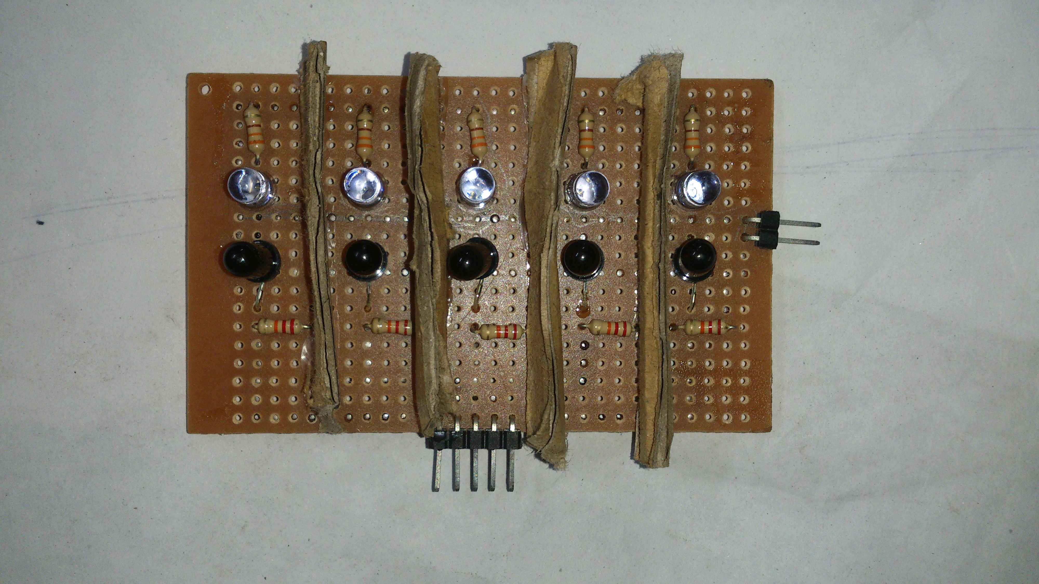
To learn the complete way of making it, you can refer to our line following and grid following tutorials.
Block detection
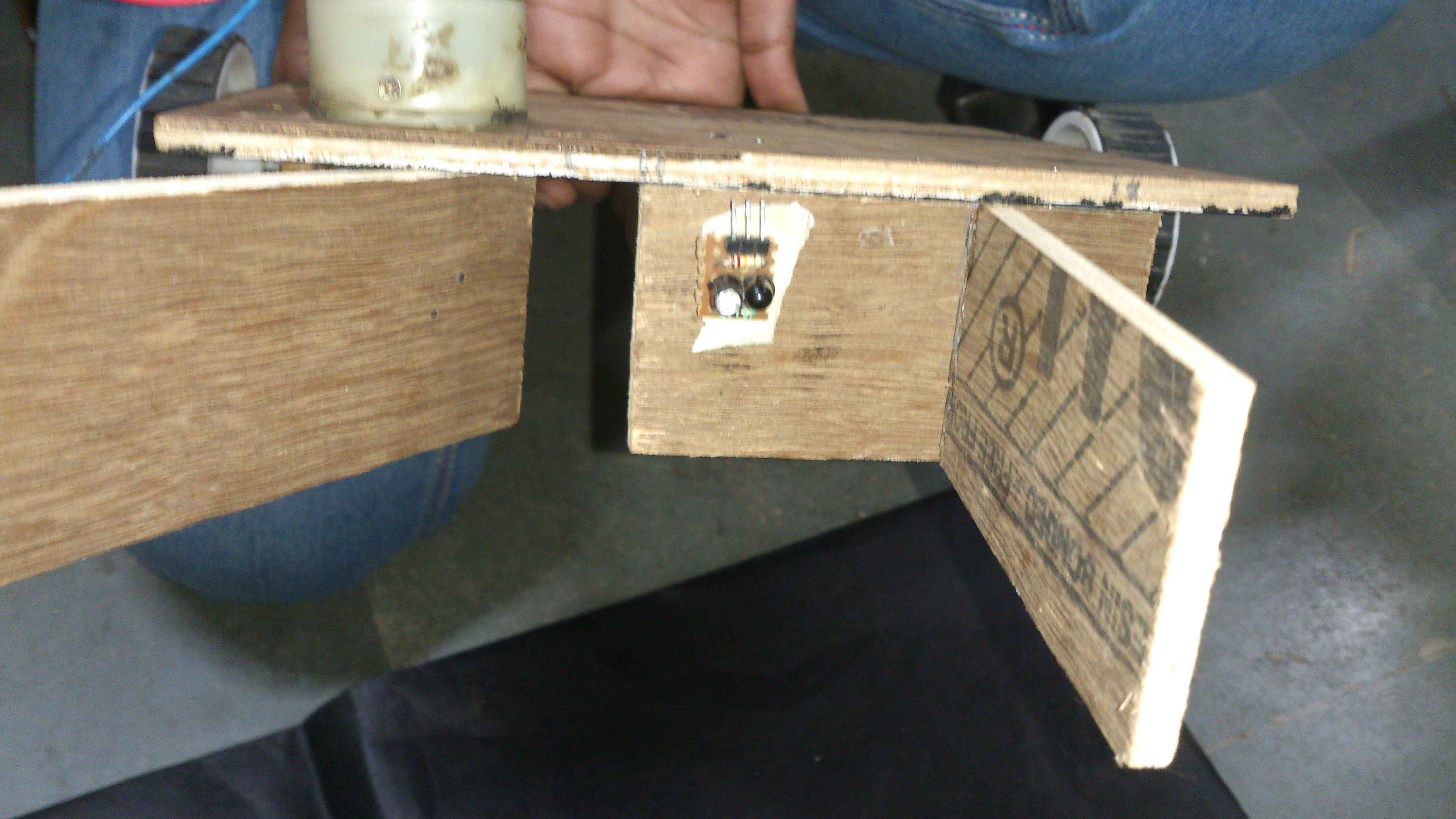
Here, we are using simple IR sensors to detect the presence of block. This sensor circuit will be placed on front of the robot as shown.

Void detection
We can use an IR sensor to detect void. This IR sensor will be placed at the bottom of the robot as shown. The circuit diagram for this will be same as above.
Node detection (while moving the block to void)
In transporter, we need to move the detected blocks to the voids and place them there. We need a provision to detect the node before reaching the node. At this state, when the block is on the node, the robot is amidst the way. The situation can be detected by placing sensors on the robot as shown in figure.

Processing:
ADC for line following sensor and object detector.
Comparator fot the rest.

Rhino board has inbuilt facility of motor driver. So, here we didn’t have to make an external motor driver circuit. However, if you are not using rhino board, you’ll have to make a motor driver circuit whose circuit diagram would look as shown below:


You can take output from any port of microcontroller and connect it to the input pins of the motor driver. You’ll require 2 L293Ds or 1 quadruple motor driver ICs because we need to run 3 motors here.
Check out tutorial on Motor Driver for further assistance.
Algorithm:
Moving block to the void:
The Brute Force algorithm for this is very simple. Since, mapping the whole grid is done, we accurately know the positions of cubes and voids. So, we have to pick one cube and then scan its surrounding for a void. The demonstration is as follows:
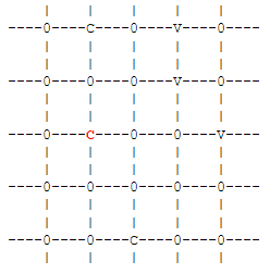
The grid is shown as follows

‘C’ represents the cube
‘C’ represents selected cube
‘V’ represents the void
‘M’ represents marked position
suppose we select the cube located at (1,2)(when top left node is considered as 0,0).
Now we will scan diametrically for void
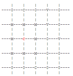
As you can see that the node surrounding the selected cube are scanned for voids. In the loop just outside the cube there are no voids present. So, we increase our radius
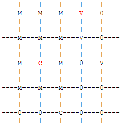
So, while scanning the next layer the void was found out at (0,3). Now, the robot will pick the cube from (1,2) and place it at the position (0,3).
Note: Here when the node is marked, the robot does not actually travel to the marked position. You can find the nearest cube in the code itself as you already know the positions of cubes and voids.
This is not the best method but this will give you results easily without much problem.
Best path to move block to void:
The Optimal solution to the shortest path algorithm is the Dijkstra’s algorithm. This can give you the shortest path even when the distance between nodes are varying (i.e. the grid is not uniform). In our case, as the grid is uniform. When Dijkstra’s algorithm is applied on a graph with uniform lengths, it behaves like BFS(Breadth First Search). So, instead of applying Dijkstra’s algorithm BFS will also perform the same task with an added advantage being faster and easier to code than the Dijkstra’s algorithm. So, all you need to do is select a cube and apply BFS. While searching when you find the void you stop the search and you got your nearest voids coordinates. The only thing left to be done is to move a cube from one location to another!!