COLOUR DETECTION MODULE
TCS 320 TCS3200
Introduction
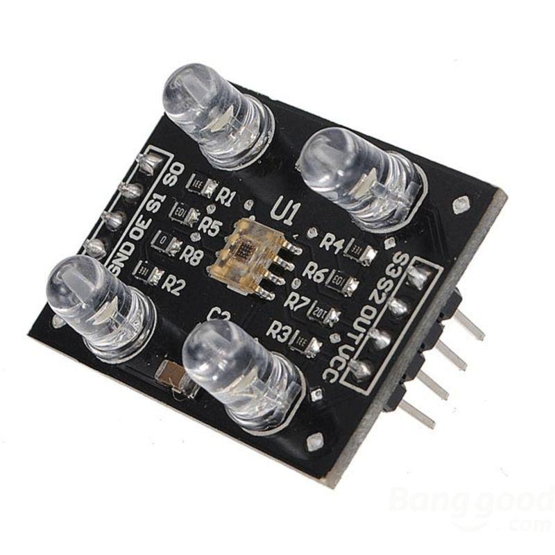
A colour detection module senses the colour of the object in front of it. The module has four LEDs. Light from these diodes gets reflected by the object to reach the colour sensor TCS230. It provides the information about the colour by splitting it into the three primary components red, green and blue. The sensor has ability of high resolution conversion of light to frequency.
Pin Configuration
The configuration of the sensor on the sensor module is as follows
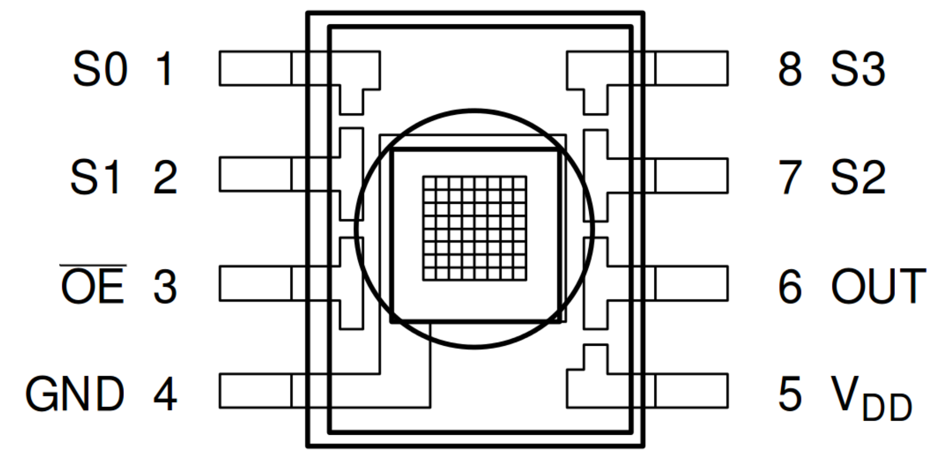
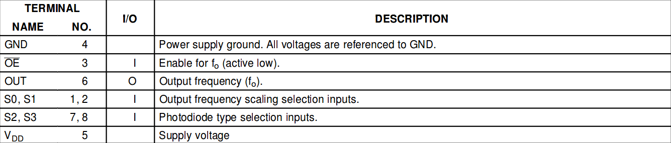
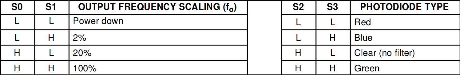
The pins S0 and S1 are used to scale output frequency. The pins S2 and S3 are used for colour detection. For eg. if we want to detect blue colour, we set S2 and S3 to logic HIGH and LOW respectively.
Working
The LED’s of the module emit white light which on reflection from the coloured objects gives the light of a specified frequency. This light is incident on the array of photodiodes. The colour sensor has a 8x8 array of photodiodes. The output of the photodiodes i.e. current is thus controlled by the frequency of the incident light. The current-to-frequency controller of sensor generates a squarewave corresponding to the current from the photodiodes. Sixteen photodiodes have blue filters, 16 photodiodes have green filters, 16 photodiodes have red filters, and 16 photodiodes are clear with no filters. The four types (colors) of photodiodes are interdigitated to minimize the effect of non-uniformity of incident irradiance. All 16 photodiodes of the same color are connected in parallel and which type of photodiode the device uses during operation is pin-selectable. The sensor is enabled until the enable pin has a logical low voltage.
Interfacing with uC
Since we know the working and pin configuration, it can be understood that the colour of the object can be detected by using the filters i.e. photodiodes on the sensor corresponding to red, green and blue in a loop to get the RGB value. The enable pin is kept high when the sensor is not in use. The supply voltage should vary between 2.7V and 5.5 V. For interfacing the sensor with ARDUINO UNO, the output of the sensor is measured using pulseIn() function.
Pseudocode
Initialize the frequency variables and define pin numbers
void setup()

{

//set the pinMode of sensor module pins

//set S0 and S1 acc to required frequency

Serial.begin(9600); //get the output on serial monitor

}

void loop()

{

	//detection of red colour

	//set both S2 and S3 to LOW

frequency=pulseIn(output pin of sensor,LOW);

Serial.print("R=")

Serial.print(frequency);

delay(100);

//similarly detect G and B

}
You may use map function to get values from 0 to 255 which is used to identify the colour in standard RGB format. If the R value is higher, we can infer that colour has more of red in it. The RGB values of colour to be detected should be matched with the output value to know if the required colour is being detected. The values may not match exactly due to physical conditions and hence you need to provide a range of values for the output to vary. You can use any colour picker application to know the correct RGB codes of the desired colour.