Crescendo
The engineers are trying to design a vehicle that is capable of traversing through a demolished area, having trenches and innumerable obstacles. You are asked to design the prototype of a bot that is capable of switching its plane of motion and also picks and places the objects using extendable gripper. The arena has many rifts and projections that must be cleared without harming the bot in any manner.
Your challenge is to build a bot manually robust enough to cross obstacles and at the same time switch its plane of motion by using suitable mechanisms.
How does this Tutorial work?
This is a guide for an enthusiast like yourself steam for this Robotix’20 edition! The tutorial lists out all the skills that this event can possibly require for your bot to complete the problem statement and tells you exactly how you can implement each of them. And finally, find our ‘Tips’ to put together all your mechanisms and build a winning that’s going to win you a ton of fun!
Problem Statement:
To build a manually controlled bot that is capable of switching its plane of motion using a suitable mechanism and pick and place objects using an extendable gripper.
To tackle this, your bot needs to have a mechanism which has:
-
Ability to traverse
-
Changing the plane of motion
-
Extendable gripper
Mechanism for changing the plane of motion
There will be many instances during the run when Bot has to change its plane of motion. The best way it can achieve this is by taking in the use of two rack and pinions or any linear actuator. This will let the bot to displace its body up and down. Rack and pinion enable the conversion of rotational motion into linear motion. So, it will definitely help you if you attach the central part of the body to the rack and pinions. It will ensure that when the motors run, the rack and pinion lifts up the main portion of the body.
It should be noted that it is quite easy to switch the place of motion vertically upward but the difficulty lies in switching to a plane downward using the same mechanism.
Mechanisms for picking and placing
The additional challenge of gripping the object and placing it increases the difficulty of the problem statement. The bot has to grip the object in such a manner that it can traverse robustly on the arena holding the object. The gripping mechanism mentioned here involves the use of a rack and pinion that allows the to and fro motion of the gripper attached to the bot at a fixed height. There will be one motor attached to the gripper in order to change the gap between the two arms of the gripper to hold the object robustly. In order to grip an object, the bot will extend the gripper and increase the gap between the two arms so as to fix the object in between.
The problem you might face during the making of this design is the balancing of bot while changing planes. But with proper calculation of torque balance with things arranged in a proper manner, this design might be a very effective one.
But in the end, it all boils down to the key point in winning any manual robotics event. That is how well you control your bot. And a lot of practice on a well-assembled bot will definitely take you a long way.
Mechanisms for traversal
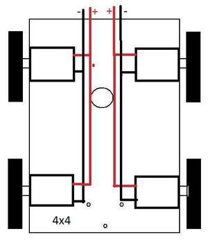
Despite all the complications that you might think your bot has after loading it with all the mechanisms we discussed, the best way to traverse with your bot remaining unaltered is employing the classic differential drive.
Differential Drive Mechanism
Design:
When two motors are connected to wheels in one line, opposite to each other (just like a pair of wheels connected to a single shaft) the speed with which each motor rotates determines the direction of motion. When both the wheels rotate at the same speed the difference between the motors is zero. This makes the robot move forward in a straight line. The robot can move in the reverse direction if the direction of rotation of both the motors are reversed. This will again be in a straight line if the speed difference is zero.

Now changing the speed of any one motor will result in movement in a direction away from the straight line. For example, reducing the speed of the right motor will result in a speed difference and hence change in direction.The resultant force is such that the robot turns right. This direction change can be controlled to required angle by further reducing the speed of the motor.Slower is the right motor, sharper is the turn to right. This is exactly the same for Left turn. As a conclusion, Slower right motor, sharper right turn. Slower left motor Sharper left turn. Below are some scenarios which explains working of differential drive mechanism.M1 and M2 are motors which drive wheels on left and right respectively.
Material Required:
-
Basic rectangular chassis
-
Four DC Motors
-
Wires
-
Four Wheels
Steps of construction
-
Make the Wheel Template.
-
Cut-out the wheels, and drill a hole in the middle.
-
Join the wheels to the chassis with connecting axles.
-
Join the motors to the wheels.
-
Make connections of your motor to the circuit of Differential drive.
-
Your robot is ready to work.
Working
-
When both the wheels turn forward with same RPM the robot goes forward
-
When both the wheels turn in reverse direction with same RPM the robot goes backward.
-
When left wheel turns forward and right wheel turns backward the robot takes zero radius right turn. Vice versa happens in the case of left turn.
-
When left wheel turns forward but right wheel turns forward with lesser RPM than left wheel then the robot takes right turn with particular radius of curvature. Vice versa happens in the case of left turn.
Controls:
Three way switch

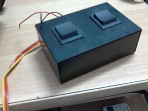
Motor connections:
The motors are fixed to the chassis and the tyres are fitted to the DC Geared Motors.