Nexus
Problem Statement:
To build an image processing robot that uses an onboard camera to detect a path formed by circles and traverses on it autonomously and is capable of shape detection and barcode reading.
Tools
-
Soldering Iron
-
Laptop
-
Visual Studio / MATLAB / Any IDE with an Image Processing Library
-
AVR programming software / Arduino IDE
-
Onboard Camera
Materials
-
2 Wheels
-
1 Castor Wheel
-
Metal Chassis
-
2 DC motors
-
1 Development Board
-
1 Microcontroller (ATmega 16/32/328)
-
1 Programmer (ISP/Arduino)
-
Motor Driver (L293D)
-
1 LED
-
Relimates
We’ll split the Problem Statement into Modules.In this tutorial, we’ll step by step discuss each module. The first thing to do is to make a mobile robot capable of moving according to instructions received from the laptop.
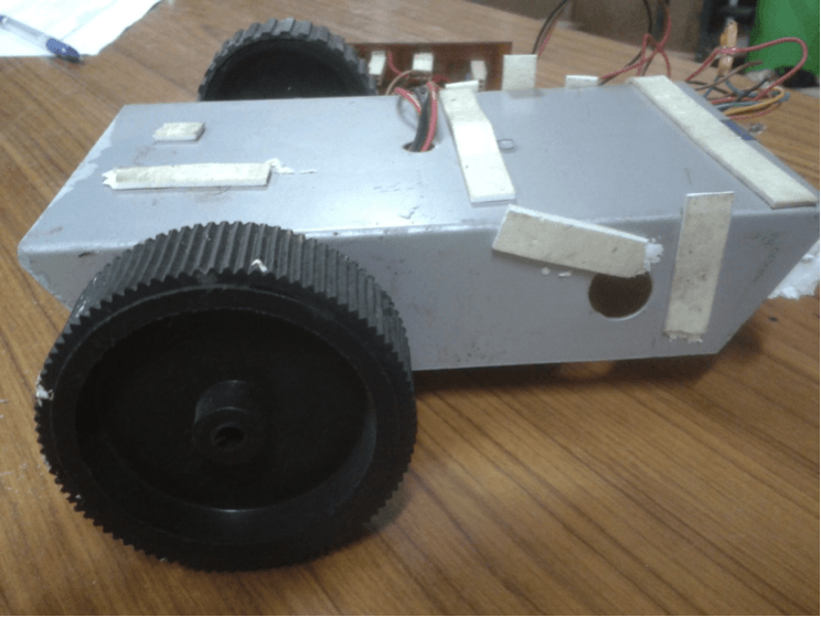
PART 1 - A REMOTE CONTROLLED ROBOT:
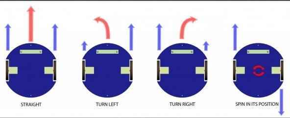
Locomotion
The robot can be made to move by using a differential drive as the base. With independent motors for the left and right sides of the base, differential drives allow the robot to move in all directions and turn as well. How the motors will rotate will be determined by the voltage supplied to the motor by the motor driver circuit, which in turn will depend on the instructions sent to the motor driver by the micro controllers. For more details on differential drives, please check Differential drive.
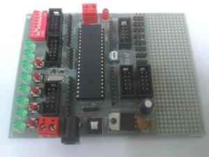
Microcontroller
Conceived to be the brain of the robot, the microcontroller is the device that allows us to control the robot and make it autonomous. By pre-programming it, we can make it give different outputs based on different inputs and instructions received, and thereby the robot acts accordingly. For a more elaborate understanding of the working of an AVR microcontroller, please visit AVR tutorials. Essentially you only need to program the microcontroller on your robot, to move in a particular direction, based on the character received by it from the laptop.
The code to be burned on arduino is as follows:
#define L_MOTOR_POSITIVE 9
#define L_MOTOR_NEGATIVE 10
#define L_MOTOR_ENABLE 3
#define R_MOTOR_POSITIVE 6
#define R_MOTOR_NEGATIVE 11
#define R_MOTOR_ENABLE 5
#define LED_PIN 13
#define MAX_SPEED_R 240
#define MAX_SPEED_L 180

/*
 * Movements:
 *     W := forward
 *     S := stop
 *     D := right
 *     A := left
 *     R := extreme right
 *     L := extreme left
 *     X := reverse
 */

void setup() {
  pinMode(9, OUTPUT);
  pinMode(10, OUTPUT);
  pinMode(3, OUTPUT);
  pinMode(11, OUTPUT);
  pinMode(6, OUTPUT);
  pinMode(5, OUTPUT);
  pinMode(LED_PIN, OUTPUT);
  Serial.begin(9600);
}

int incomingByte = Serial.read();

void loop() {
  if (Serial.available() > 0) {
    incomingByte = Serial.read();

    Serial.print("I received: ");
    Serial.println(incomingByte);
    if (incomingByte == 'A') {
      digitalWrite(L_MOTOR_POSITIVE, LOW);
      digitalWrite(L_MOTOR_NEGATIVE, LOW);

      digitalWrite(R_MOTOR_POSITIVE, HIGH);
      digitalWrite(R_MOTOR_NEGATIVE, LOW);

      analogWrite(L_MOTOR_ENABLE, MAX_SPEED_L);
      analogWrite(R_MOTOR_ENABLE, MAX_SPEED_R);
    }
    else if (incomingByte == 'D') {
      digitalWrite(L_MOTOR_POSITIVE, HIGH);
      digitalWrite(L_MOTOR_NEGATIVE, LOW);

      digitalWrite(R_MOTOR_POSITIVE, LOW);
      digitalWrite(R_MOTOR_NEGATIVE, LOW);

      analogWrite(L_MOTOR_ENABLE, MAX_SPEED_L);
      analogWrite(R_MOTOR_ENABLE, MAX_SPEED_R);
    }
    else if (incomingByte == 'W') {
      digitalWrite(L_MOTOR_POSITIVE, HIGH);
      digitalWrite(L_MOTOR_NEGATIVE, LOW);

      digitalWrite(R_MOTOR_POSITIVE, HIGH);
      digitalWrite(R_MOTOR_NEGATIVE, LOW);

      analogWrite(L_MOTOR_ENABLE, MAX_SPEED_L);
      analogWrite(R_MOTOR_ENABLE, MAX_SPEED_R);


      else if (incomingByte == 'B') {
      digitalWrite(R_MOTOR_POSITIVE, LOW);
      digitalWrite(R_MOTOR_NEGATIVE, LOW);

      digitalWrite(L_MOTOR_POSITIVE, LOW);
      digitalWrite(L_MOTOR_POSITIVE, LOW);

      digitalWrite(13, HIGH);
      delay(1000);
      digitalWrite(13, LOW);
    }
  }
}
Part 2 : COMPUTER VISION
Before proceeding with this module, we would request you to go through the set of general tutorials for computer vision, for both MATLAB and OpenCV, also found on our website. It is quite extensive, and we will assume that a working knowledge, as put forward there, is in the grasp of the reader of this tutorial. Note that the video feed will contain some noise. Therefore you will not have a perfect image, and hence detection may become really difficult or you might get wrong predictions. Therefore it is advised to use filters to smoothen your image.
Perspective Conversion using Homography
Firstly, the front view obtained from the camera should be converted into a bird-eye view. This would enable effective performance of further tasks such as contour & colour detection. This can be done using a Homography matrix. A Homography is a transformation (a 3 x 3 matrix) that maps the points in one image to the corresponding points in the other image. To calculate a homography between two images, you need to know at least 4 point correspondences between the two images. If you have more than 4 corresponding points, it is even better. OpenCV will robustly estimate a homography that best fits all corresponding points.
Colour Detection
First thing that needs to be done is that all shapes and obstacles need to be identified. We can start with colour detection. Have separate windows for each colour so that only shapes with the required colours are displayed in the respective window.
Detecting Contours
We need to scan the shapes present in the arena using an onboard camera. A good approach to solve this problem would be to segment out the shapes from the image that is taken by the camera and using only the bottom half of the image as our required Region of Interest. Use bounding rectangles to take out the portion of the image containing the shapes. A method called contour detection can be used to figure out the bounding rectangle. The same thing is supposed to be done for the shapes in the given image also.
Detecting Shapes
The function approxPolyDP approximate a curve or a polygon with another curve/polygon with less vertices so that the distance between them is less than or equal to the specified precision. It uses the Douglas-Peucker algorithm
Barcode Scanning
For this, using homography to get a new image consisting of only the barcode would be a good approach. After this, one can measure the size of the blue contours and accordingly decode the barcode.
Path Planning
Greedily following the nearest circle would suffice for normal traversal. In round 1, on encountering a triangle obstacle however, we can narrow down our region of interest to the right of the triangle. On encountering a square obstacle however, we can narrow down our region of interest to the left of the square. In round 2, in the case of a rectangular obstacle , the barcode on it has to be scanned and accordingly path has to be chosen.