Tesseract
To build an autonomous robot capable of traversing through the arena through a safe and optimized path generated by solving algorithms on data transmitted by RFID cards, to reach the end point.
USP
-
Autonomous Traversal (Line following)
-
RFID Reading
-
Path Planning and Optimization
Component List
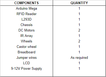
Line follower
IR LED Pair
Working- IR sensor or an infrared sensor consists of an IR LED coupled with a photodiode. This pair is generally called an IR pair or photocoupler. An infrared sensor emits infrared radiations which are detected by the photodiode. Resistance of photodiode changes according to the amount of IR radiation falling on it, hence changing the voltage drop against it. Further, by using the voltage comparator (like LM358) we can sense the voltage change and generate the output accordingly.
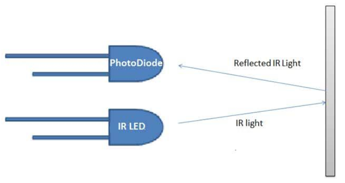
Usage - To follow a line, we can use the difference in reflectivity of the line and surface.
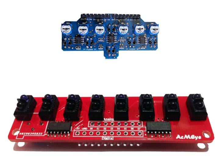
IR Sensor Array
For better accuracy we can use multiple IR LED pairs in an IR sensor array.
RFID
RFID Reading
RFID or Radio Frequency Identification system consists of two main components, a transponder/tag attached to an object to be identified, and a transceiver also known as interrogator/reader.
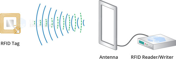
A Reader consists of a radio frequency module and an antenna which generates high frequency electromagnetic field. The tag is usually a passive device, meaning it doesn’t contain a battery. Instead it contains a microchip that stores and processes information, and an antenna to receive and transmit a signal.
To read the information encoded on a tag, it is placed in close proximity to the Reader (does not need to be within direct line-of-sight of the reader). A Reader generates an electromagnetic field which causes electrons to move through the tag’s antenna and subsequently power the chip.
The powered chip inside the tag then responds by sending its stored information back to the reader in the form of another radio signal. This is called backscatter. The backscatter, or change in the electromagnetic/RF wave, is detected and interpreted by the reader which then sends the data out to a computer or microcontroller.
Hardware Overview – RC522 RFID Reader/Writer Module
The RC522 RFID module based on MFRC522 IC from NXP usually comes with an RFID card tag and key fob tag having 1KB memory. And it can also write a tag.
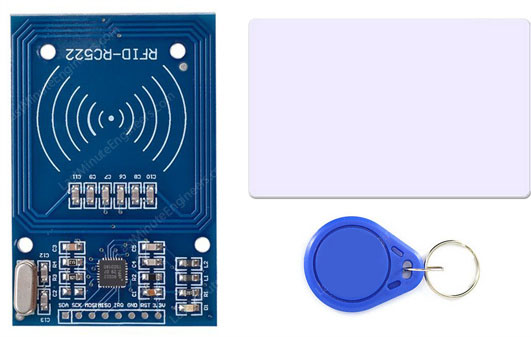
The RC522 RFID Reader module is designed to create a 13.56MHz electromagnetic field that it uses to communicate with the RFID tags (ISO 14443A standard tags). The reader can communicate with a microcontroller over a 4-pin Serial Peripheral Interface (SPI) with a maximum data rate of 10Mbps. It also supports communication over I2C and UART protocols.
RC522 RFID Module Pinout
The RC522 module has total 8 pins that interface it to the outside world. The connections are as follows:
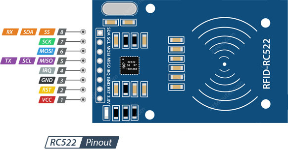
- VCC supplies power for the module. This can be anywhere from 2.5 to 3.3 volts.
- RST is an input for Reset and power-down. When this pin goes low, hard power-down is enabled. This turns off all internal current sinks including the oscillator and the input pins are disconnected from the outside world. On the rising edge, the module is reset.
- GND is the Ground Pin and needs to be connected to the GND pin on the Arduino.
- IRQ is an interrupt pin that can alert the microcontroller when RFID tag comes into its vicinity.
- MISO / SCL / Tx pin acts as Master-In-Slave-Out when SPI interface is enabled, acts as serial clock when I2C interface is enabled and acts as serial data output when UART interface is enabled.
- MOSI (Master Out Slave In) is SPI input to the RC522 module. SCK (Serial Clock) accepts clock pulses provided by the SPI bus Master i.e. Arduino.
- SS / SDA / Rx pin acts as Signal input when SPI interface is enabled, as serial data when I2C interface is enabled and as serial data input when UART interface is enabled. This pin is usually marked by encasing the pin in a square so it can be used as a reference for identifying the other pins. Now hook up the Arduino to the RFID reader, and download the required MFRC522 library.
MIFARE Classic 1K Memory Layout
The 1K memory of the Tag is organized in 16 sectors (from 0 to 15) Each sector is further divided into 4 blocks (block 0 to 3). Each block can store 16 bytes of data (from 0 to 15).
That means we have- 16 sectors x 4 blocks x 16 bytes of data = 1024 bytes = 1K memory The whole 1K memory with sectors, blocks and data is highlighted below.
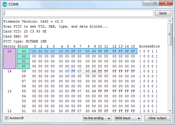
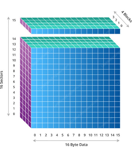
The Block 3 of each sector is called Sector Trailer and contains information called Access Bits to grant read and write access to remaining blocks in a sector. That means only the bottom 3 blocks (block 0, 1 & 2) of each sector are actually available for data storage. The Block 0 of sector 0 is known as Manufacturer Block/Manufacturer Data contains the IC manufacturer data, and the Unique IDentifier (UID).
In order to read data from the card, we need to define an array of 18 bytes named readbackblock[18]. This can be used to read the written contents back.The MIFARE_Read method in MFRC522 library requires a buffer that is at least 18 bytes to hold the 16 bytes of a block.
Pseudo Code The above are the internal details of how RFID Card readings work. However, using the library given in the event description (https://github.com/miguelbalboa/rfid), without specifying the block number the integer value can be obtained.
#include <SPI.h>
#include <MFRC522.h>

#define RST_PIN         5
#define SS_PIN          53

MFRC522 mfrc522(SS_PIN, RST_PIN);

void setup() {
  Serial.begin(9600);
  SPI.begin();
  mfrc522.PCD_Init();
  Serial.println(F("Read personal data on a MIFARE PICC:"));
}

void loop() {

  MFRC522::MIFARE_Key key;
  for (byte i = 0; i < 6; i++) key.keyByte[i] = 0xFF;
  byte block;
  byte len;
  MFRC522::StatusCode status;

  if ( ! mfrc522.PICC_IsNewCardPresent()) {
    return;
  }

  if ( ! mfrc522.PICC_ReadCardSerial()) {
    return;
  }

  byte buffer1[18];

  block = 4;
  len = 18;

  status = mfrc522.PCD_Authenticate(MFRC522::PICC_CMD_MF_AUTH_KEY_A, 4, &key, &(mfrc522.uid));
  if (status != MFRC522::STATUS_OK) {
    Serial.print(F("Authentication failed: "));
    Serial.println(mfrc522.GetStatusCodeName(status));
    return;
  }

  status = mfrc522.MIFARE_Read(block, buffer1, &len);
  if (status != MFRC522::STATUS_OK) {
    Serial.print(F("Reading failed: "));
    Serial.println(mfrc522.GetStatusCodeName(status));
    return;
  }

//int num = atoi((const char*) buffer1);

//  Serial.print(num);		// This num will contain 0

  byte buffer2[18];
  block = 1;

  status = mfrc522.PCD_Authenticate(MFRC522::PICC_CMD_MF_AUTH_KEY_A, 1, &key, &(mfrc522.uid)); //line 834
  if (status != MFRC522::STATUS_OK) {
    Serial.print(F("Authentication failed: "));
    Serial.println(mfrc522.GetStatusCodeName(status));
    return;
  }

  status = mfrc522.MIFARE_Read(block, buffer2, &len);
  if (status != MFRC522::STATUS_OK) {
    Serial.print(F("Reading failed: "));
    Serial.println(mfrc522.GetStatusCodeName(status));
    return;
  }

int num2 = atoi((const char*) buffer2); // num2 will contain the integer that is stored in the RFID card

  Serial.println(num2);

  delay(1000);

  mfrc522.PICC_HaltA();
  mfrc522.PCD_StopCrypto1();
}