Video Tutorial
Introduction
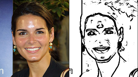
As the name suggests, edge detection is a means to locate the edges of objects in a particular image. This has applications in detecting corners, sharp turn, and in identifying shapes. Edge detection has a lot of scope for precision and efficiency, and there are many well-developed algorithms to deal with it. Here we will be studying a more basic conversion which will help us understand the concepts of edge detection.
In this program, we use the gray-scale equivalents of the pixels, which represent the intensity of the pixel, for our edge detection. We cycle through each pixel, and check all the 8 pixels around it, in a sub-unit of 3X3. We store the highest value of the brightness and the lowest value of the difference. If the difference between the highest and the lowest value is greater than a particular threshold, then that particular pixel is considered to belong to an edge, and in the resultant image, we designate as black (part of an edge). Otherwise we designate it white. The final edge-detected image is a binary image where the black portions represent the edges.
The figure shown below shows a rather rudimentary example of edge detection:
General Edge Detection
**PROGRAM
Given below is a function which takes as parameters an image and the threshold, and returns the image with only edges, based on the threshold
UNDERSTANDING THE CODE
The above function is a modular one, for the purpose of edge detection. The image to be worked upon is given as a parameter, as is the threshold which will be used for our algorithm. In the function, we accept these parameters and create the other variables needed for it.
With the nested for loops, we cycle through each pixel of the loaded image. Then we have another nested for loop of 3 iterations each to focus on the sub-unit around the pixel [i,j]. The maximum and minimum values of the gray-scale equivalents are computed and if the difference between them is higher than the threshold, as has been explained, the pixel in the resultant binary image is assigned 0 to indicate black or part of an edge, or otherwise 255 to indicate white or not an edge.
Finally, the resultant image is returned to the calling function.);j++){;i++){**
Canny Edge Detection
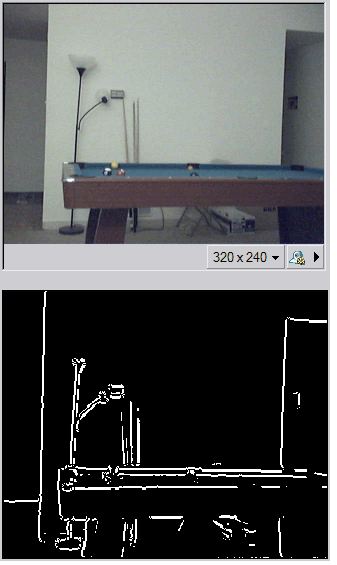
This is one of the most efficient and successful edge detection methods. It utilizes a multi-stage algorithm, operating on the gray-scale version of the image under consideration. The algorithm involves computations of the rate of change of pixel values in any particular direction. If the change is very high, then, similar to the basic algorithm we discussed before, the pixel is expected to be part of an edge. The algorithm also checks whether the gradient is a local maxima at that point, which helps it to be more precise. The thresholds of this edge detector are also very important.
The upper threshold specifies the value above which a gradient would definitely be considered part of an edge. As for the lower threshold, gradients below it are to be discarded entirely, while values in between the two are to be investigated for possible edge linking, i.e if nearby pixels happen to be part of an edge or not, and if they fulfil other criteria.
PROGRAM
The program below utilizes Canny edge detection on the frames of a video
UNDERSTANDING THE CODE
Till the initialization of the variable frame, the code is similar to the one before. In this case, however, we need one more image variable other than the result, and that is an intermediate to store the grayscale equivalent of the frame. Both of these variables must, for the purpose of being used in pre-defined functions, be initialized with the cvCreateImage function, which requires the dimensions of the frame to be known. To avoid taking a separate frame for initialization outside the while loop, we are creating the two other image variables inside the loop itself, using them for edge detection, displaying them and releasing them from memory before repeating the operation.
The cvCanny function takes the first parameter as the grayscale image it has to operate upon; the second parameter is the destination image and the next two parameters are the lower and upper thresholds respectively. The final parameter is the size of the kernel for gradient computation, which is usually taken as 3. The resultant image is shown in the window and the action is repeated like before. A point to note is that in Canny edge detection, the edges are shown in white and the background in black.
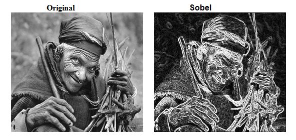
Sobel Edge Detection
This is another widely used edge detection method that utilizes the Sobel operator, which calculates the approximate opposite of the gradient of the image intensity function. It also works on grayscale images as input. It uses something called convolution kernels of dimensions usually 3X3 for the purpose of getting the gradient at each point, in principle similar to the approach we used for our rudimentary method.
The gradients in the direction of each axis are used for determining whether the pixel is part of an edge or not.
PROGRAM
The program given below depicts the utilisation of the Sobel Edge detection method
UNDERSTANDING THE CODE
Most of the program is largely similar to the Canny Edge detection one, so we will focus only on the differences. One of the major variations is that the Sobel edge detection function requires the destination image to have a larger depth than the source one. So we must make ‘edgeframe’ the 16-bit intermediate in this case to store the result of the Sobel operation. Moreover, a 16-bit signed image cannot be shown with the cvShowImage function properly. So we have to convert it back to 8-bit unsigned format. To save memory space and code lines, we use the variable for the grayscale intermediate to also store the final resultant image, thus calling it gscale_res.
The 16-bit signed image is converted to the 8-bit unsigned version through the cvConvertScaleAbs() function. We will not go into the details of this particular function as it will not be needed anywhere else. The first two parameters are the source and destination image, and the next two should be 1 and 0 respectively. After the images are generated, they are shown as in the Canny edge detection program.